

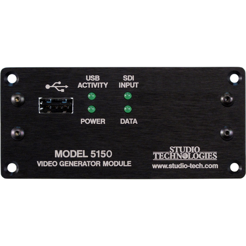
Studio Technologies Model 5150-02 Video Generator Module with Optical Input/Output
Availability:
Special Order ItemThis item is not stocked and needs to be ordered from the manufacturer. Please contact our sales team for more information.
Description
Model 5150 with Optical Input/Output, 1310 nm.
The Model 5150 Video Generator Module is a unique device suited for a variety of custom broadcast, post-production, industrial, and corporate multimedia installations. As a member of the 5100-Series of modules, the Model 5150's compact size belies its powerful video feature set. Advanced circuitry within the Model 5150 supports the generation of a broadcast-standard high-definition SDI signal. And rather than reproducing a fixed test pattern, the Model 5150 has the capability to store and output two custom video images. The images, one for "720" and one for "1080," are based on bitmap (.bmp) files that can be created using a personal computer's graphics program. For convenience, the .bmp files are loaded into the module's non-volatile memory via a standard USB flash drive. The appropriate "720" or "1080" image is automatically connected to the SDI output whenever an SDI input signal is not present. This ensures that an SDI output signal is always sent to equipment further along the signal chain.
The Model 5150's video signal generation capability can be extremely useful, serving as both a "keep-alive" signal as well as allowing a detailed graphics image to be displayed for identification purposes. When a valid HD- or 3G-SDI signal is connected to the module's input it will pass through, unchanged, to the module's SDI output. Only when an input is not present will the custom image be generated. The format and rate of the custom image will match that of the previously-connected SDI input signal. This "learning" capability allows a Model 5150 to automatically adapt to the SDI format and rate utilized by a specific facility or application.
An alternate operating mode can be selected, allowing the Model 5150 to serve as a dedicated video signal generator. In this mode an SDI signal connected to the module will serve as an external timing reference.
General Highlights
Applications for the Model 5150 include sports broadcasting booth packages, "POV" (point-of-view) remote-controlled camera systems, stadium video interface (I/O) locations, and government/corporate facilities. The module's performance is completely "pro" with video quality, reliability, and installation flexibility matching that of much larger-scale equipment.
For operation the Model 5150 only requires connection of a few signals. These consist of SDI inputs and outputs, an external source of nominal 12 Vdc and, optionally, two wires associated with a local RS-485 data bus. Some applications may also utilize the general-purpose input (GPI) and general-purpose output (GPO) functions (available only on modules with serial numbers 00251 and later). Coaxial SDI input and output support is standard. Optical input and output support is optional. The acceptable DC input voltage range is 10 to 18, allowing a variety of power sources to be utilized.
The Model 5150 uses standard connectors for fast, convenient interfacing. Coaxial SDI input and output signals use BNC connectors. An optional video SFP fiber optic module can be installed at the factory. The module supports interconnection of single-mode optical fibers using LC plugs. The DC power input and data bus connections use a 4-position, 0.1-inch header. The GPI and GPO connections use a 3-position, 0.1-inch header. Low-cost IDC (insulation-displacement connector) mating sockets allow simple interconnection with a variety of wire gauges. Four status LEDs offer users both performance confidence and troubleshooting assistance.
The Model 5150 is compatible with the Studio Technologies' Model 5190 Remote Access Module. This will allow remote configuration, monitoring and control, via an Ethernet connection, of key module operating and status parameters. A local RS-485 data bus allows up to 16 of the 5100-Series modules to be connected to a Model 5190.
Several Model 5150 operating parameters can be configured to meet the needs of specific applications. A USB flash drive along with several DIP switches, are used to convey the configuration to the module. A simple text file that reflects the desired configuration is created and stored on the USB flash drive. When inserted into the appropriate socket on the Model 5150 the file is read and stored. Updating the Model 5150's firmware (embedded software) is also possible using a USB flash drive loaded with factory-supplied files.
Model 5150 Video Generator Modules do not include a mounting enclosure or chassis. They are intended for mounting in custom 19-inch rack panels, equipment boxes, broadcast furniture, "NEMA" I/O boxes, or other specialized enclosures. It is expected that integration firms will create applications that use Model 5150 modules as part of complete broadcast, production, corporate, and government solutions. Sophisticated users will be able to easily create "one-off" solutions to solve unique challenges.
SDI Inputs and SDI Outputs
High-definition SMPTE-compatible SDI signals with data rates of 1.485 Gb/s nominal (HD-SDI) and 2.97 Gb/s nominal (3G-SDI) can be connected. Virtually all of the commonly-utilized "720" and "1080" formats are supported. Standard-definition SDI signals with a data rate of 270 Mb/s nominal (SD-SDI) are not supported. It was felt that users looking for advanced solutions such as those provided by the Model 5150 will not typically be working with SD-SDI signals. But be assured that many HD-SDI and 3G-SDI formats and rates are supported, allowing the Model 5150 to be appropriate for worldwide use.
Coaxial (BNC) Support
Using standard BNC connectors, the Model 5150 supports one coaxial SDI input and one coaxial SDI output.
Optical Fiber Support
Factory-implemented options allow the Model 5150 to support SDI signals that are transported using single-mode optical fibers. Using video SFP modules a range of optical input, output, and transceiver capabilities can be supported.
The standard 1310 nanometer optical transmit wavelength is available, as are the more-esoteric CWDM wavelengths. A module that includes an optical SDI output will always have its optical output active, transporting the same SDI data as that present on the coaxial (BNC) output. When a Model 5150 has been provided with an optical SDI input a configuration choice selects whether it, or the coaxial (BNC) input, is active.
Video Generation Capability
During typical operation an HD- or 3G-SDI signal is connected to the Model 5150's selected SDI input. It's then "passed through" to the module's SDI output(s) and on to the next part of the signal chain. But what happens when the external SDI signal is not present? That's when the Model 5150's internal SDI generator becomes active. When a signal is not present on the selected SDI input the module will generate a high-definition (HD- or 3G-SDI) image that will serve as a "slate," ID, or "SDI-active" signal.
From the factory two bitmap (.bmp) image files are stored in non-volatile memory. One file is used for generating the image for 1280 x 720 pixel formats and the other for 1920 x 1080 pixel formats. But alternate bitmap image files can be created and stored in the Model 5150. These alternate images can supply site- or application-specific information useful to "downstream" users. Using a personal-computer graphics program, such as Microsoft® Paint® or Adobe® Photoshop®, generating custom images and storing them in the appropriate bitmap format is a simple matter.
A USB port, located on the Model 5150's front panel, allows direct connection of a standard USB flash drive. If the Model 5150's firmware (embedded software) recognizes compatible FAT32 bitmap (.bmp) files on the USB flash drive they will be automatically loaded into non-volatile memory. The USB flash drive can then be removed with the custom images safely stored within the Model 5150.
One subtle but important feature has been included for broadcast applications which use the Model 5150's SDI output(s) "on-air." When an SDI signal is removed from the module's selected SDI input, the Model 5150 will output a few seconds of solid-gray color before the stored image appears. This will help to ensure that technicians or operators will be visually "warned" that the module's input signal has been lost and that the custom image will soon be taking its place. It's hoped that the gray video image will be innocuous for on-air viewers yet different enough to encourage operators to switch the module's output away from being "on air."
A unique feature of the Model 5150 is its ability to automatically adapt to the format and rate of a connected SDI signal. This allows the custom image to be output at the same format and rate as that used by the associated network, local facility, or event. If, for example, a connected input is "1080i/59.94" then the Model 5150 will automatically detect and store that information. From then on whenever an SDI input signal is not present the internal generator will output the custom image at "1080i/59.94." Changing the format and rate of the generator only requires connection of an SDI signal with the desired characteristics. (A minimum required connection time helps to ensure that an accidental format/rate change won't occur.) However, there may be situations where maintaining the format and rate of the internally-generated signal is important. To support this condition one configuration choice allows the automatic format/rate selection function to be disabled.
Video Generation with External Reference
Some applications may benefit from the Model 5150 serving as a full-time stand alone video generator. A configuration choice helps to support such applications by using the selected SDI input only as a timing reference. Unlike typical operation, when selecting this operating mode a signal connected to the selected SDI input would not pass through to the SDI. Its rate, format, and specific timing characteristics would be used as a reference for the internally-generated video output. Note that bi-level or tri-level analog timing reference signals are not supported. Only a HD-SDI or 3G-SDI signal can serve as a reference signal for the Model 5150.
GPI and GPO
Model 5150 modules with serial numbers 00251 and later offer a general-purpose input (GPI) and a general-purpose output (GPO) function. The GPI allows the connection of a switch or relay contact to control the on/off status of a Model 5150 function. Future versions of the firmware may implement a GPI-controlled action.
The GPO function provides an indication of the status of the selected SDI input. It's intended that the GPO will be connected to an LED indicator. A configuration choice selects whether the GPO is active (+3.3 V) when the selected SDI input is valid or active when the selected SDI input is invalid. (This can also be described as active "high" or active "low.") This allows, for example, a green LED to light whenever a valid signal is connected to the selected SDI input, thus providing an "input good" indication. Alternately, a red LED could light when the selected SDI input is not active, providing an "input fail" indication.
| SDI Compatibility, Supported Formats and Rates | HD-SDI per SMPTE ST 292:2011: 720p: 50, 59.94, 60 1080i: 50, 59.94, 60 1080p: 23.98, 24, 25, 29.97, 30 1080psf: 23.98, 24, 25 3G-SDI Level A per SMPTE ST 424:2006 and ST 425:2011: 1080p: 50, 59.94, 60 SD-SDI per SMPTE¨ ST 259:2008: Not supported |
| Coaxial (BNC) SDI Input and Output | Type: unbalanced Impedance: 75 ohms Level: 800 mV p-p, nominal |
| Optical Input (optional) | Compliance: SMPTE ST 297:2006 (as applicable) Fiber Type: single mode Wavelengths Supported: 1250 to 1650 nm Receive Sensitivity: Ð17 dBm, nominal @ 2.97 Gb/s Maximum Input Power: Ð3 dBm, nominal |
| Optical Output (optional) | Compliance: SMPTE ST 297:2006 (as applicable) Fiber Type: single mode Wavelength: 1310 nm (FP laser) or CWDM (DFB laser), as per order Launch Power: Ð3 dBm, nominal Typical Fiber Interconnect Length: 10 km minimum |
| GPI | active low, "pulled up" to 3.3 Vdc using 5 k ohm resistor; activates on closure to common (applies to Model 5150 modules with serial numbers 00251 and later) |
| GPO | active high, 3.3 Vdc with series resistance of 150 ohm; short circuit current of approximately 22 mA in reference to common (applies to Model 5150 modules with serial numbers 00251 and later) |
| Remote Control Data Interface | RS-485 115.2 Kb/s, 8-1-N; compatible with Studio Technologies' Model 5190 Remote Access Module |
| Connectors | Coaxial SDI Input and Output: BNC, 3G-SDI optimized, gold plating on center pin, per IEC 61169-8 Annex A Optical Module: MSA-compliant SFP DC Input/Data: 1, 4-position male header; refer to Appendix B in the User Guide for mating connector details GPI/GPO: 1, 3-position male header (applies to modules with serial numbers 00251 and later); refer to Appendix B in the User Guide for mating connector details |
| Power Requirement | 12 Vdc nominal, 400 mA max; acceptable range 10-18 Vdc, 480 mA max at 10 V |
| Dimensions (Overall) | 3.75 inches wide (9.5 cm) 1.69 inches high (4.3 cm) 2.30 inches deep (5.8 cm) |
| Mounting | requires custom implementation; no mounting method provided; refer to Appendix C in the User Guide for details |
| Weight | 0.2 pounds (91 g) |
Your home for all things pro audio—backed by expertise and experience. Connect with us today.
Your home for all things pro audio—backed by expertise and experience. Connect with us today.