
%20products%20and%20prevents%20overlo...
)

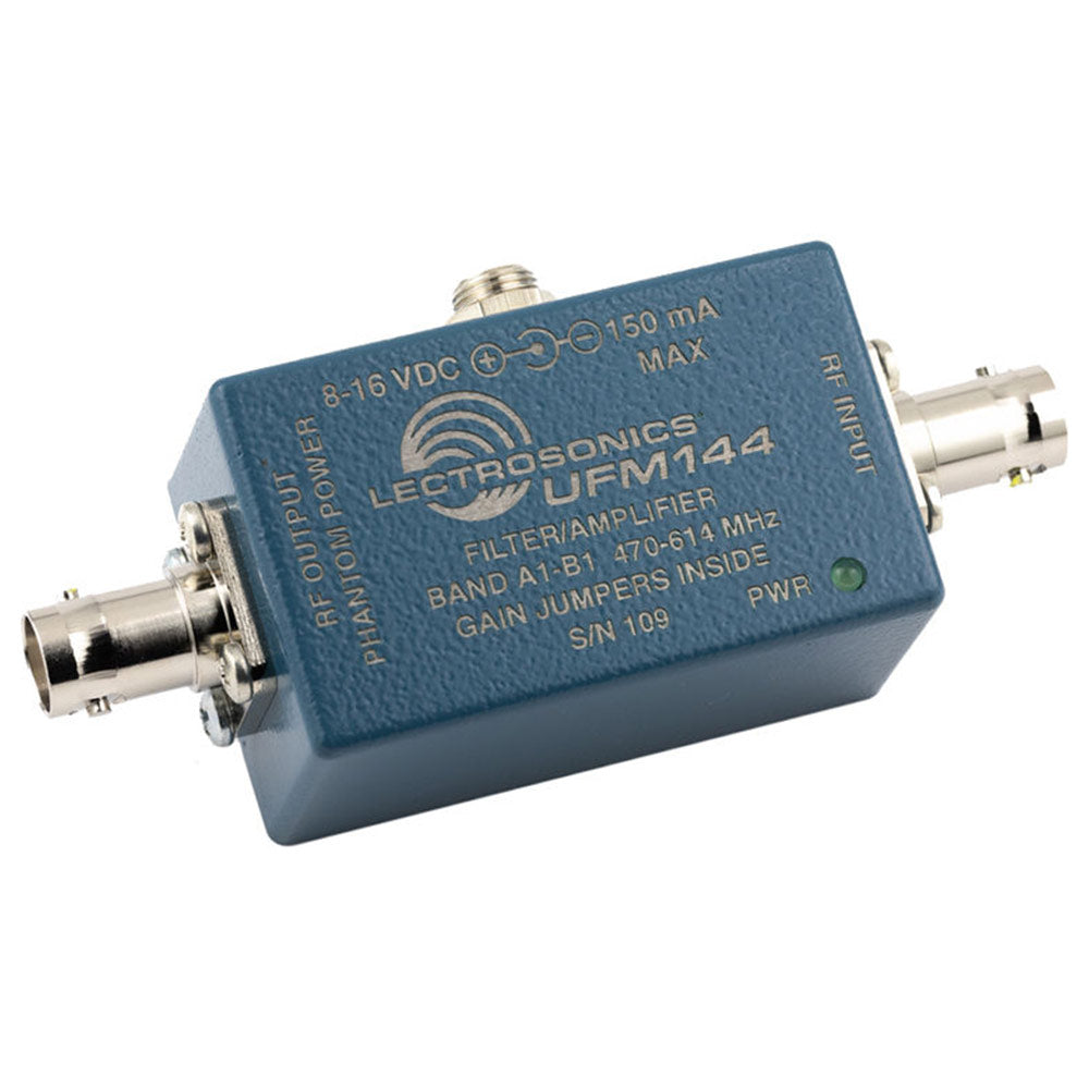
Lectrosonics UFM144 - UHF Filter and Amplifier Inline Module (470 - 614 MHz)
Availability:
Special Order ItemThis item is not stocked and needs to be ordered from the manufacturer. Please contact our sales team for more information.
Description
The UFM144 is used to configure antenna systems requiring long cable runs or distribution to multiple receivers. RF filtering before gain minimizes intermodulation (IM) products and prevents overload. Two transmission line ceramic resonators at the input provide filtering with a 144 MHz bandwidth, followed by 12dB of gain using a high quality GaAsFET RF amplifier with an excellent +41dBm output IP3.
Power can be applied to a side panel connector, or from DC bias on the RF output jack from a receiver or multicoupler. A switching regulator is used in the power supply to control current consumption over an input voltage range of 8 to 16 volts. The regulator maintains low current consumption and low heat dissipation which is especially useful in mobile field production applications.
The housing is constructed of cast aluminum with a brushed aluminum cover plate. Two rugged BNC connectors and a threaded, locking power jack provide secure connections for reliability in field production and longterm installations.
The RF amplifier is fixed at 12 dB of gain. Adjustments to the gain are made by inserting attenuators. The gain can be adjusted to +12dB, +8dB or +5dB using the 0, -4 and -7 jumpers. Remove the four screws and the bottom cover for access to the internal connections and jumpers.
Features:
- 144 MHz passband from 470 to 614 MHz
- Ceramic resonator filters
- GaAsFET RF amplifier
- +27 dBm (input) and +41 dBm (output) 3rd Order Intercept
- Switching regulator for 8-16V power at constant power dissipation to minimize heat
- Jumpers set gain at +5dB, +8dB or +12dB
- Powered from external DC source or DC bias from Lectrosonics multicouplers and Venue Series receivers
| Third Order Intercept | Input IP3 = +27 dBm (+41 dBm output) |
| Connectors | RF IN: 50 ohm BNC DC IN: 2.1 mm locking power jack RF OUT (phantom power in): 50 ohm BNC |
| Freq Range | 470 - 614 MHz |
| Filter Bandwidth | 144 MHz, factory set. |
| RF Gain | +12 dB with 0dB attenuator +8 dB with 4dB attenuator +5 dB with 7dB attenuator |
| Power Requirements | 8V to 16V DC at the input jack; auto reset poly fuse protection circuit; constant power switching supply ´ 8V DC (125 to 145 mA) ´ 12V DC (83 to 106 mA) ´ 14.4V DC (69 to 89 mA) ´ 16V DC (60 to 80 mA) |
| DC Bias/Phantom Powering | DC voltage supplied via coaxial cable by UMC16B or VRM input jack or BIAS-T power inserter (70 to 80 mA) |
| Power Consumption | 1 Watt nominal (switching regulator) |
| Dimensions | 2.26 x 1.39 x 1.14 inches (not including BNC connectors) |
| Weight | 3.3 ozs.; 94 grams |
Your home for all things pro audio—backed by expertise and experience. Connect with us today.
Your home for all things pro audio—backed by expertise and experience. Connect with us today.