

Sonifex S1 - Digital / Analog Hybrid Broadcast Radio Mixer
Availability:
Special Order ItemThis item is not stocked and needs to be ordered from the manufacturer. Please contact our sales team for more information.
Description
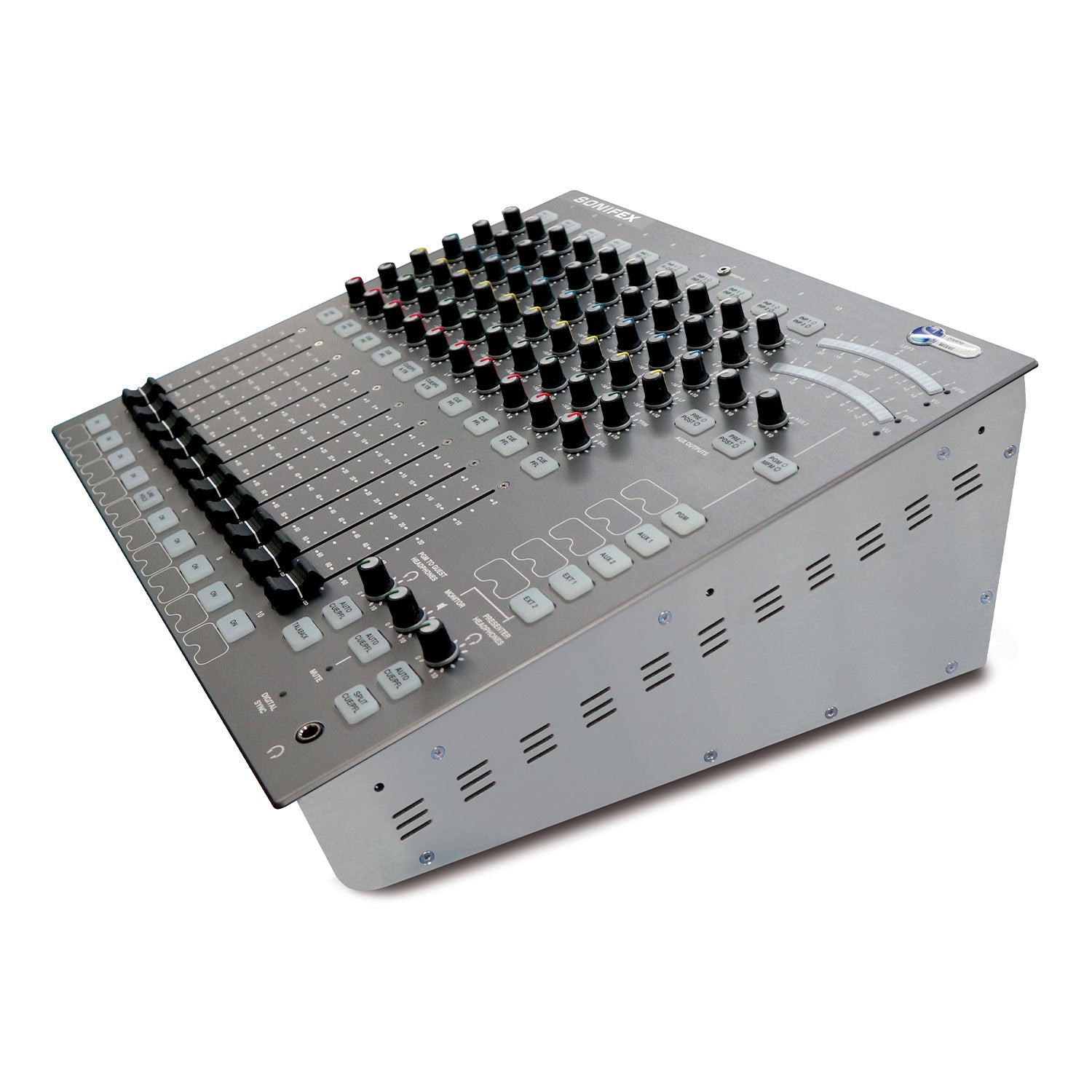
The S1 has an amazing feature set and offers a proper broadcast solution to community, educational and student radio stations that need a versatile, reliable radio broadcast mixer. It has a 'no compromise on quality' approach with excellent mic amps, comprehensive facilities and simple, reliable operation. The Sonifex S1 mixer is a high performance compact, low cost, fixed format mixing console designed for on-air radio use. It can be fitted flush into a desk-top or can be rack-mounted by the addition of optional rack ears. The rear connectivity panel can be rotated 90˚ onto the base of the unit providing easier connection to the unit when it is rack-mounted. It has an integral universal switch mode power supply, which uses an IEC inlet. It maintains the same front panel ease of use found on the Sonifex S2 whilst providing advanced automated features not seen on any other product currently available on the market.
Features:
- High performance, ultra-reliable on-air radio mixer.
- Low cost.
- Easy to use.
- Small footprint, flush-mounting or rack-mounting.
- Analogue and digital inputs and outputs.
- Main stereo output buss plus 2 Aux output buses, pre or post fader selectable.
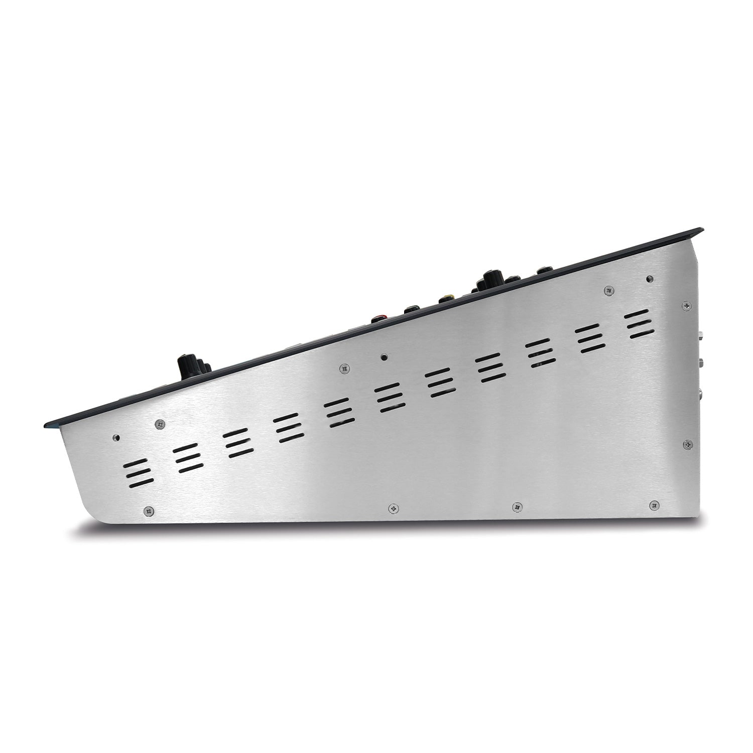
- Rotating rear panel for ease of installation.
- Integrated power supply.
- Remote outputs per channel.
- Fader start of ancilliary equipment such as CD players.
- Programmable general purpose I/O.
- Monitor muting on mic live.
- Mic-live/on-air sign switching.
- Monitor outputs for presenter and guest headphones, and speakers.
- Bright LED meter display PPM/VU selectable with separate meterbridge output.
- 100mm ALPS long-throw faders with control via VCAs.
- Separate telco and stereo cleanfeed o/ps for use with a telephone hybrid and codec respectively.
- Advanced automation facilities.
- Remote control via free SCi software.
The console consists of ten input channels:
- 2 x mono XLR mic/mono XLR line inputs.
- 1 x mono XLR mic/mono XLR telco input.
- 2 x mono XLR mic/mono XLR line inputs/ stereo ¼" jack unbalanced line input.
- 1 x stereo XLR line/stereo XLR cleanfeed input.
- 2 x stereo XLR line/stereo RCA inputs, one with a 3.5mm stereo aux input.
- 2 x stereo XLR line/stereo SPDIF and Toslink digital inputs.
Providing in total 5 mic, 4 mono line, 10 stereo analogue, 2 stereo digital, 1 telco and 1 stereo cleanfeed inputs which you can switch between.
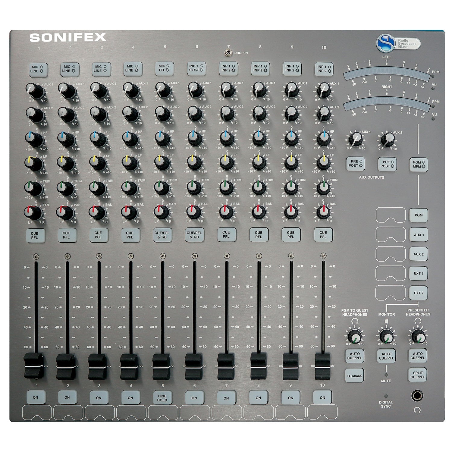
Wide-Ranging Input Channels
Input source buttons at the top of each channel strip are used to route the connected source to the mixer buses.
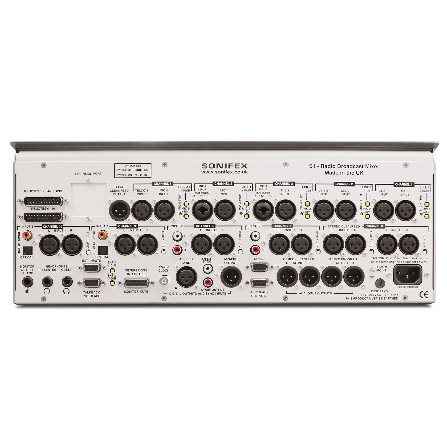
All of the balanced XLR input connectors have a 10dB gain switch on the rear panel for use with unbalanced or low level input sources. The XLR microphone inputs have individual +48V phantom power switches and a gain calibration potentiometer providing up to 65dB of gain for the preamp.
Input channels 1 and 2 have 2 separate XLRs for microphone and balanced line input sources.
Input channels 3 and 4 use an XLR and a combination XLR/stereo jack connector to allow a microphone input and both a balanced mono or an unbalanced stereo line input to be used.
Input channel 5 acts as microphone input or as a telco input with a dedicated cleanfeed output, with available line hold remote for connection to a telephone hybrid.
Input channel 6 is a balanced stereo line input on XLR together with a stereo cleanfeed input on balanced XLR for use with ISDN codecs.
Input channels 7 and 8 have stereo balanced XLRs and stereo unbalanced phonos on the rear and channel 7 also has a 3.5mm insert jack socket on the front panel for use with an mp3 player/iPod.
Input channels 9 and 10 provide a stereo analogue XLR input and stereo digital S/PDIF and TOSLink optical inputs.
Any channel which has the fader up and the ON button selected is routed to the main PGM output(s).
Gain for each channel is trimmed by the front panel TRIM control providing ± 12dB of gain.
Equalisation is provided on every input channel, allowing up to 7dB cut and boost at HF (6.5 kHz) and LF (100Hz). A PAN/BAL(ance) control is available to facilitate stereo imaging.
The use of VCAs controlled by the ALPS long throw 100mm faders give a smooth, repeatable response and ensures tight stereo tracking while eliminating mechanical and electronic noise.
Analogue and Digital Outputs
The S1 has a multitude of output connectivity: one balanced stereo XLR PGM output, two balanced stereo AUX outputs on a 9-way D-type socket, a mono clean feed output on balanced XLR (for use with a telephone hybrid), a stereo cleanfeed output on stereo balanced XLRs (for use with an ISDN/IP codec) and monitor outputs for presenter headphones, guest headphones and loudspeakers. Additional outputs are provided for talkback on a 9-way D-type socket and metering using a 15-way D-type socket.
A digital stereo PGM output is provided in XLR AES/EBU or phono S/PDIF formats. The output can be referenced to an internal clock source between 32 kHz and 96 kHz or external synchronisation sources can be connected via S/PDIF, AES/EBU or BNC wordclock. The illuminated DIGITAL SYNC LED shows when the digital output is locked to either an internal or external clock.
Two Auxiliary Buses
The S1 has two Auxiliary buses that can be configured in either pre-fade or post-fade mode. Each channel can be routed to these buses using the potentiometers provided on each channel strip. Each AUX output has a trim control knob operating between fully attenuated and unity gain. Aux buses can be used for a wide range of purposes including recording telephone conversations, generating different mixes for output, connecting to audio processing equipment and much more.
Comprehensive Monitoring
The control room loudspeakers, presenter's headphones, and guest headphones are on 6.35mm stereo jack sockets. Front panel control knobs are used to vary the monitor and headphone levels and the presenter's headphones can be plugged in to the front and rear of the mixer. The control room monitor loudspeaker and headphone levels are variable between 0 (cut off) and 10 (max). An illuminated MUTE LED shows when a live microphone channel has muted the speakers and there are two pairs of MUTE contact outputs available to illuminate a 'MIC LIVE' light.
A five way electronically interlocking switch bank selects the source routed to the speakers and presenter's headphones from either of two external inputs (EXT 1, EXT 2), the PGM, or AUX Outputs. The buttons illuminate to show the selected source, PGM, AUX 1 and AUX 2 in green, EXT 1 and EXT 2 in red. The external inputs can be used for monitoring an off air signal or another studio output.
Green illuminated AUTO CUE/PFL buttons adjacent to each level control allow the monitoring of PFL when an input channel has been selected to CUE/PFL, either to the monitors or headphones.
For the Presenter headphones, SPLIT CUE/PFL can be selected which places the selected source in mono in one ear and PFL in mono in the other.
A pair of bright 21 segment LED meters can be configured to show either VU or PPM metering. The meters show either the PGM output or the selection heard in the presenter's headphones, selectable by PGM/MFM (Meter Follows Monitor) button.
Talkback
A separate TALKBACK button is provided to allow the Presenter to talk to a Guest. The S1 uses input channel one as the talkback source. Global talkback can also be configured (see the Programmable GPIO section) to allow every mic channel to communicate with the Presenter and Guest headphones.
A separate TALKBACK 9-way D-type socket on the rear panel can be used to connect the talkback output and input to and from other studios.
Configurable Remotes Per Channel
The remote outputs for each channel are highly configurable providing every possible option required to interface your external equipment to the mixer. Each channel input has its own START and STOP remote controls, except the microphone inputs which have only START outputs. (If you wanted a MIC stop control signal, you could configure this using a GPIO). Each remote can be configured to be triggered from a variety of sources, including the ON button and the CUE/PFL Button. The remotes can be set-up to be either pulsed or continuous latched outputs, and if in pulsed mode the ON button has the capability to produce repeated start pulses on additional ON button presses, when the channel is ON with the fader up.
In the case of the Telco and Stereo Cleanfeed outputs you may want to generate start and stop remotes independently of the position of the fader, so that the hybrid or codec can be triggered to connect before the channel is opened. This is possible in 'Telco Mode' where a 'start' is sent when the ON button is initially pressed and a 'stop' is sent when the ON button is pressed again, turning the channel selection off. In addition the channel can be configured to show the state of the external equipment, e.g. using a tally back GPI signal from an automation system, the ON button can flash green when the end of a song is being reached.
Programmable GPIOs
The S1 also has five General Purpose Inputs/Outputs (GPIO's) available. Each input/output has been designed to be very versatile and almost any operation with the mixer can be achieved when utilising them. A GPI can be configured using the SCi software to perform up to 10 different operations from a single input. For example, in an automated playout situation, you may want to:
- Force 4 channels ON with the faders forced up.
- Force 4 channels to stereo Line Input.
- Mute the Control Room Monitors.
This configuration would use 9 of the 10 operations available for an individual GPI.
The GPOs are equally powerful. The outputs can be configured to be pulsed or continuous, and active high or low. An output can be generated based on actions required. For example, a GPO can be configured to generate a global talkback function with a set-up so that:
- When Mic 2, Mic 3 and Mic 4 are all not live, generate a GPO continuous output.
The GPO could then be linked back into one of the GPI's with the input configured to:
- Force PFL on Mics 2, 3 and 4.
- Enable Auto CUE/PFL on Guest H/phones
This would allow the guests to freely talk to each other until one of their microphones goes live. This is just an example of the potential uses of the programmable GPIOs.
Remote Control / Configuration Using SCi Software
The S1 mixer is highly configurable and has numerous options allowing the mixer configuration to be tailored to your requirements. Using the freely available Sonifex SCi software, every parameter of the mixer can be set up with ease. This product has settings that can be adjusted using the Sonifex SCi (Serial Control Interface) software.
| Input / Output Impedances | |
| Mic Input: | > 1k5½ electronically balanced |
| Mono Line Input: | > 20k½ electronically balanced |
| Stereo Line Input: | > 20k½ electronically balanced |
| PGM Output: | < 50½ electronically balanced |
| Monitor Outputs: | < 75½ unbalanced |
| AES Input/Output: | 110½ |
| S/PDIF Input/Output: | 75½ |
| BNC Wordclock Input: | 50½ |
| Input / Output Gain Range | |
| Mic Input: | Preset pot +21dB to +64dB ref -50dBu, TRIM pot ± 12dB |
| Mono Line Input: | Switch 0dB to +10dB ref 0dBu, TRIM pot ± 12dB |
| Stereo Line Input: | Switch 0dB to +10dB ref 0dBu, TRIM pot ± 12dB |
| Telco Input: | Switch 0dB to +10dB ref 0dBu, TRIM pot ± 12dB |
| Stereo Cleanfeed Input: | Switch 0dB to +10dB ref 0dBu, TRIM pot ± 12dB |
| Digital Input: | 0dBFS = +18dBu on input; TRIM pot ± 12dB allowing 0dBu to +24dBu |
| Digital Output: | 0dBFS = +18dBu |
| Frequency Response | |
| Mic Input: | 40Hz to 20kHz Ð1dB, +0dB |
| Line Inputs: | 20Hz to 20kHz Ð0.5dB, +0dB |
| RCA Inputs: | 20Hz to 20kHz Ð0.5dB, +0dB |
| Noise (20Hz to 20kHz) | |
| Mic Input E.I.N.: | -130dB with 150½ source. |
| Stereo Inputs | -92dBu ref 0dB (fader down, no routing) -91dBu (fader down, one channel routed) -86 dBu (unity gain, one channel routed) -83 dBu (unity gain, two channels routed) |
| Distortion | |
| Total Harmonic Distortion: | 0.015% at 1kHz, 0dBu 0.015% at 10kHz, 0dBu |
| Crosstalk | |
| Inter-Channel: | < -80dBu typically |
| Equalisation | |
| LF: | Shelving at 100Hz ± 7dB |
| HF: | Shelving at 6.5kHz ± 7dB |
| Range | |
| Pan Range: | Off/-3dB centre/off |
| Balance Range: | ± 6dB |
| Common Mode Rejection Ratio | |
| Mic Input: | >60dB typically |
| Digital I/O | |
| Sync Input Sample Rate Range: | 32kHz Ð 96kHz |
| Output Sample Rates: | 32kHz, 44.1kHz, 48kHz, / 96kHz (Using Onboard Clock) |
| Output Sample Width: | 24 bit |
| Output | |
| Headphone Output Load: | >45 ohms, recommended 400 |
| Maximum Output (Analogue): | +26dBu balanced into 2k or greater |
| Rear Panel Switches | |
| Phantom Power: | +48V individual per mic input |
| Gain Switch: | +10dB per XLR balanced mono / stereo input / EXT 1, EXT 2 inputs |
| Input / Output Connections | |
| Analogue Inputs: | 5 x Microphone XLR 3 pin sockets 2 x Mono line XLR 3 pin sockets 2 x Mono/stereo line combi XLR 3 pin sockets / 6.35mm stereo jack sockets 1 x Telco XLR 3 pin socket 5 x Stereo line pairs XLR 3 pin sockets 2 x Stere line pairs phono sockets 1 x Stereo cleanfeed pair XLR 3 pin sockets 1 x Stereo insert, 3.5mm jack socket |
| Digital Inputs: | 2 x S/PDIF phono sockets, 2 x TOSLink optical connectors |
| Analogue Outputs: PGM: AUX: TELCO: STEREO CLEANFEED: |
2 x XLR 3 pin plug (balanced) 9-way 'D'-type socket (balanced) XLR 3 pin plug (balanced) 2 x XLR 3 pin plug (balanced) |
| Monitor Outputs: | 6.35mm stereo jack sockets (2 x Presenter, 1 x Guest, 1 x Monitor) |
| Digital Outputs: | AES/EBU XLR 3 pin plug (balanced) or S/PDIF phono socket. |
| Digital Sync Inputs: | Wordclock on BNC, AES/EBU on XLR socket and S/PDIF on phono socket. |
| EXT Inputs: | 9-way 'D'-type socket |
| Mono Remotes: | 25-way 'D'-type plug |
| Stereo Remotes: | 25-way 'D'-type plug |
| Meterbridge Port: | 15-way 'D'-type socket |
| Talkback Interface: | 9-way 'D'-type socket |
| RS232 Serial Port: | 9-way 'D'-type socket |
| Mains Input: | Filtered IEC, continuously rated 85-264VAC, 47-63Hz, 45w nominal, 50w peak |
| Fuse Rating: | Anti-surge fuse 2A 20 x 5mm |
| Equipment Type | |
| S1: | S1 radio broadcast mixer |
| Physical Specification | |
| Dimensions (Raw): | 44.5cm (W) x 40.0cm (D) x 15.6cm (H) 17.5" (W) x 15.75" (D) x 6.1" (H) |
| Dimensions (Boxed): | 63cm (W) x 57cm (D) x 35cm (H) 24.80" (W) x 22.44" (D) x 13.78" (H) |
| Cut-Out Dimensions: | 44.0cm, 17.3" (W) x 38.1cm, 15" (D) both dims +0.2cm, -0cm |
| Weight: | Nett: 12.0kg Gross: 13.6kg Nett: 24.4lb Gross: 29.9lb |
| Accessories | |
| S1-RCK: | Optional S1 9U rack ears. |
The S1 has an amazing feature set and offers a proper broadcast solution to community, educational and student radio stations that need a versatile, reliable radio broadcast mixer. It has a 'no compromise on quality' approach with excellent mic amps, comprehensive facilities and simple, reliable operation. The Sonifex S1 mixer is a high performance compact, low cost, fixed format mixing console designed for on-air radio use. It can be fitted flush into a desk-top or can be rack-mounted by the addition of optional rack ears. The rear connectivity panel can be rotated 90˚ onto the base of the unit providing easier connection to the unit when it is rack-mounted. It has an integral universal switch mode power supply, which uses an IEC inlet. It maintains the same front panel ease of use found on the Sonifex S2 whilst providing advanced automated features not seen on any other product currently available on the market.
Features:
- High performance, ultra-reliable on-air radio mixer.
- Low cost.
- Easy to use.
- Small footprint, flush-mounting or rack-mounting.
- Analogue and digital inputs and outputs.
- Main stereo output buss plus 2 Aux output buses, pre or post fader selectable.
- Rotating rear panel for ease of installation.
- Integrated power supply.
- Remote outputs per channel.
- Fader start of ancilliary equipment such as CD players.
- Programmable general purpose I/O.
- Monitor muting on mic live.
- Mic-live/on-air sign switching.
- Monitor outputs for presenter and guest headphones, and speakers.
- Bright LED meter display PPM/VU selectable with separate meterbridge output.
- 100mm ALPS long-throw faders with control via VCAs.
- Separate telco and stereo cleanfeed o/ps for use with a telephone hybrid and codec respectively.
- Advanced automation facilities.
- Remote control via free SCi software.
The console consists of ten input channels:
- 2 x mono XLR mic/mono XLR line inputs.
- 1 x mono XLR mic/mono XLR telco input.
- 2 x mono XLR mic/mono XLR line inputs/ stereo ¼" jack unbalanced line input.
- 1 x stereo XLR line/stereo XLR cleanfeed input.
- 2 x stereo XLR line/stereo RCA inputs, one with a 3.5mm stereo aux input.
- 2 x stereo XLR line/stereo SPDIF and Toslink digital inputs.
Providing in total 5 mic, 4 mono line, 10 stereo analogue, 2 stereo digital, 1 telco and 1 stereo cleanfeed inputs which you can switch between.
Wide-Ranging Input Channels
Input source buttons at the top of each channel strip are used to route the connected source to the mixer buses.
All of the balanced XLR input connectors have a 10dB gain switch on the rear panel for use with unbalanced or low level input sources. The XLR microphone inputs have individual +48V phantom power switches and a gain calibration potentiometer providing up to 65dB of gain for the preamp.
Input channels 1 and 2 have 2 separate XLRs for microphone and balanced line input sources.
Input channels 3 and 4 use an XLR and a combination XLR/stereo jack connector to allow a microphone input and both a balanced mono or an unbalanced stereo line input to be used.
Input channel 5 acts as microphone input or as a telco input with a dedicated cleanfeed output, with available line hold remote for connection to a telephone hybrid.
Input channel 6 is a balanced stereo line input on XLR together with a stereo cleanfeed input on balanced XLR for use with ISDN codecs.
Input channels 7 and 8 have stereo balanced XLRs and stereo unbalanced phonos on the rear and channel 7 also has a 3.5mm insert jack socket on the front panel for use with an mp3 player/iPod.
Input channels 9 and 10 provide a stereo analogue XLR input and stereo digital S/PDIF and TOSLink optical inputs.
Any channel which has the fader up and the ON button selected is routed to the main PGM output(s).
Gain for each channel is trimmed by the front panel TRIM control providing ± 12dB of gain.
Equalisation is provided on every input channel, allowing up to 7dB cut and boost at HF (6.5 kHz) and LF (100Hz). A PAN/BAL(ance) control is available to facilitate stereo imaging.
The use of VCAs controlled by the ALPS long throw 100mm faders give a smooth, repeatable response and ensures tight stereo tracking while eliminating mechanical and electronic noise.
Analogue and Digital Outputs
The S1 has a multitude of output connectivity: one balanced stereo XLR PGM output, two balanced stereo AUX outputs on a 9-way D-type socket, a mono clean feed output on balanced XLR (for use with a telephone hybrid), a stereo cleanfeed output on stereo balanced XLRs (for use with an ISDN/IP codec) and monitor outputs for presenter headphones, guest headphones and loudspeakers. Additional outputs are provided for talkback on a 9-way D-type socket and metering using a 15-way D-type socket.
A digital stereo PGM output is provided in XLR AES/EBU or phono S/PDIF formats. The output can be referenced to an internal clock source between 32 kHz and 96 kHz or external synchronisation sources can be connected via S/PDIF, AES/EBU or BNC wordclock. The illuminated DIGITAL SYNC LED shows when the digital output is locked to either an internal or external clock.
Two Auxiliary Buses
The S1 has two Auxiliary buses that can be configured in either pre-fade or post-fade mode. Each channel can be routed to these buses using the potentiometers provided on each channel strip. Each AUX output has a trim control knob operating between fully attenuated and unity gain. Aux buses can be used for a wide range of purposes including recording telephone conversations, generating different mixes for output, connecting to audio processing equipment and much more.
Comprehensive Monitoring
The control room loudspeakers, presenter's headphones, and guest headphones are on 6.35mm stereo jack sockets. Front panel control knobs are used to vary the monitor and headphone levels and the presenter's headphones can be plugged in to the front and rear of the mixer. The control room monitor loudspeaker and headphone levels are variable between 0 (cut off) and 10 (max). An illuminated MUTE LED shows when a live microphone channel has muted the speakers and there are two pairs of MUTE contact outputs available to illuminate a 'MIC LIVE' light.
A five way electronically interlocking switch bank selects the source routed to the speakers and presenter's headphones from either of two external inputs (EXT 1, EXT 2), the PGM, or AUX Outputs. The buttons illuminate to show the selected source, PGM, AUX 1 and AUX 2 in green, EXT 1 and EXT 2 in red. The external inputs can be used for monitoring an off air signal or another studio output.
Green illuminated AUTO CUE/PFL buttons adjacent to each level control allow the monitoring of PFL when an input channel has been selected to CUE/PFL, either to the monitors or headphones.
For the Presenter headphones, SPLIT CUE/PFL can be selected which places the selected source in mono in one ear and PFL in mono in the other.
A pair of bright 21 segment LED meters can be configured to show either VU or PPM metering. The meters show either the PGM output or the selection heard in the presenter's headphones, selectable by PGM/MFM (Meter Follows Monitor) button.
Talkback
A separate TALKBACK button is provided to allow the Presenter to talk to a Guest. The S1 uses input channel one as the talkback source. Global talkback can also be configured (see the Programmable GPIO section) to allow every mic channel to communicate with the Presenter and Guest headphones.
A separate TALKBACK 9-way D-type socket on the rear panel can be used to connect the talkback output and input to and from other studios.
Configurable Remotes Per Channel
The remote outputs for each channel are highly configurable providing every possible option required to interface your external equipment to the mixer. Each channel input has its own START and STOP remote controls, except the microphone inputs which have only START outputs. (If you wanted a MIC stop control signal, you could configure this using a GPIO). Each remote can be configured to be triggered from a variety of sources, including the ON button and the CUE/PFL Button. The remotes can be set-up to be either pulsed or continuous latched outputs, and if in pulsed mode the ON button has the capability to produce repeated start pulses on additional ON button presses, when the channel is ON with the fader up.
In the case of the Telco and Stereo Cleanfeed outputs you may want to generate start and stop remotes independently of the position of the fader, so that the hybrid or codec can be triggered to connect before the channel is opened. This is possible in 'Telco Mode' where a 'start' is sent when the ON button is initially pressed and a 'stop' is sent when the ON button is pressed again, turning the channel selection off. In addition the channel can be configured to show the state of the external equipment, e.g. using a tally back GPI signal from an automation system, the ON button can flash green when the end of a song is being reached.
Programmable GPIOs
The S1 also has five General Purpose Inputs/Outputs (GPIO's) available. Each input/output has been designed to be very versatile and almost any operation with the mixer can be achieved when utilising them. A GPI can be configured using the SCi software to perform up to 10 different operations from a single input. For example, in an automated playout situation, you may want to:
- Force 4 channels ON with the faders forced up.
- Force 4 channels to stereo Line Input.
- Mute the Control Room Monitors.
This configuration would use 9 of the 10 operations available for an individual GPI.
The GPOs are equally powerful. The outputs can be configured to be pulsed or continuous, and active high or low. An output can be generated based on actions required. For example, a GPO can be configured to generate a global talkback function with a set-up so that:
- When Mic 2, Mic 3 and Mic 4 are all not live, generate a GPO continuous output.
The GPO could then be linked back into one of the GPI's with the input configured to:
- Force PFL on Mics 2, 3 and 4.
- Enable Auto CUE/PFL on Guest H/phones
This would allow the guests to freely talk to each other until one of their microphones goes live. This is just an example of the potential uses of the programmable GPIOs.
Remote Control / Configuration Using SCi Software
The S1 mixer is highly configurable and has numerous options allowing the mixer configuration to be tailored to your requirements. Using the freely available Sonifex SCi software, every parameter of the mixer can be set up with ease. This product has settings that can be adjusted using the Sonifex SCi (Serial Control Interface) software.
| Input / Output Impedances | |
| Mic Input: | > 1k5½ electronically balanced |
| Mono Line Input: | > 20k½ electronically balanced |
| Stereo Line Input: | > 20k½ electronically balanced |
| PGM Output: | < 50½ electronically balanced |
| Monitor Outputs: | < 75½ unbalanced |
| AES Input/Output: | 110½ |
| S/PDIF Input/Output: | 75½ |
| BNC Wordclock Input: | 50½ |
| Input / Output Gain Range | |
| Mic Input: | Preset pot +21dB to +64dB ref -50dBu, TRIM pot ± 12dB |
| Mono Line Input: | Switch 0dB to +10dB ref 0dBu, TRIM pot ± 12dB |
| Stereo Line Input: | Switch 0dB to +10dB ref 0dBu, TRIM pot ± 12dB |
| Telco Input: | Switch 0dB to +10dB ref 0dBu, TRIM pot ± 12dB |
| Stereo Cleanfeed Input: | Switch 0dB to +10dB ref 0dBu, TRIM pot ± 12dB |
| Digital Input: | 0dBFS = +18dBu on input; TRIM pot ± 12dB allowing 0dBu to +24dBu |
| Digital Output: | 0dBFS = +18dBu |
| Frequency Response | |
| Mic Input: | 40Hz to 20kHz Ð1dB, +0dB |
| Line Inputs: | 20Hz to 20kHz Ð0.5dB, +0dB |
| RCA Inputs: | 20Hz to 20kHz Ð0.5dB, +0dB |
| Noise (20Hz to 20kHz) | |
| Mic Input E.I.N.: | -130dB with 150½ source. |
| Stereo Inputs | -92dBu ref 0dB (fader down, no routing) -91dBu (fader down, one channel routed) -86 dBu (unity gain, one channel routed) -83 dBu (unity gain, two channels routed) |
| Distortion | |
| Total Harmonic Distortion: | 0.015% at 1kHz, 0dBu 0.015% at 10kHz, 0dBu |
| Crosstalk | |
| Inter-Channel: | < -80dBu typically |
| Equalisation | |
| LF: | Shelving at 100Hz ± 7dB |
| HF: | Shelving at 6.5kHz ± 7dB |
| Range | |
| Pan Range: | Off/-3dB centre/off |
| Balance Range: | ± 6dB |
| Common Mode Rejection Ratio | |
| Mic Input: | >60dB typically |
| Digital I/O | |
| Sync Input Sample Rate Range: | 32kHz Ð 96kHz |
| Output Sample Rates: | 32kHz, 44.1kHz, 48kHz, / 96kHz (Using Onboard Clock) |
| Output Sample Width: | 24 bit |
| Output | |
| Headphone Output Load: | >45 ohms, recommended 400 |
| Maximum Output (Analogue): | +26dBu balanced into 2k or greater |
| Rear Panel Switches | |
| Phantom Power: | +48V individual per mic input |
| Gain Switch: | +10dB per XLR balanced mono / stereo input / EXT 1, EXT 2 inputs |
| Input / Output Connections | |
| Analogue Inputs: | 5 x Microphone XLR 3 pin sockets 2 x Mono line XLR 3 pin sockets 2 x Mono/stereo line combi XLR 3 pin sockets / 6.35mm stereo jack sockets 1 x Telco XLR 3 pin socket 5 x Stereo line pairs XLR 3 pin sockets 2 x Stere line pairs phono sockets 1 x Stereo cleanfeed pair XLR 3 pin sockets 1 x Stereo insert, 3.5mm jack socket |
| Digital Inputs: | 2 x S/PDIF phono sockets, 2 x TOSLink optical connectors |
| Analogue Outputs: PGM: AUX: TELCO: STEREO CLEANFEED: |
2 x XLR 3 pin plug (balanced) 9-way 'D'-type socket (balanced) XLR 3 pin plug (balanced) 2 x XLR 3 pin plug (balanced) |
| Monitor Outputs: | 6.35mm stereo jack sockets (2 x Presenter, 1 x Guest, 1 x Monitor) |
| Digital Outputs: | AES/EBU XLR 3 pin plug (balanced) or S/PDIF phono socket. |
| Digital Sync Inputs: | Wordclock on BNC, AES/EBU on XLR socket and S/PDIF on phono socket. |
| EXT Inputs: | 9-way 'D'-type socket |
| Mono Remotes: | 25-way 'D'-type plug |
| Stereo Remotes: | 25-way 'D'-type plug |
| Meterbridge Port: | 15-way 'D'-type socket |
| Talkback Interface: | 9-way 'D'-type socket |
| RS232 Serial Port: | 9-way 'D'-type socket |
| Mains Input: | Filtered IEC, continuously rated 85-264VAC, 47-63Hz, 45w nominal, 50w peak |
| Fuse Rating: | Anti-surge fuse 2A 20 x 5mm |
| Equipment Type | |
| S1: | S1 radio broadcast mixer |
| Physical Specification | |
| Dimensions (Raw): | 44.5cm (W) x 40.0cm (D) x 15.6cm (H) 17.5" (W) x 15.75" (D) x 6.1" (H) |
| Dimensions (Boxed): | 63cm (W) x 57cm (D) x 35cm (H) 24.80" (W) x 22.44" (D) x 13.78" (H) |
| Cut-Out Dimensions: | 44.0cm, 17.3" (W) x 38.1cm, 15" (D) both dims +0.2cm, -0cm |
| Weight: | Nett: 12.0kg Gross: 13.6kg Nett: 24.4lb Gross: 29.9lb |
| Accessories | |
| S1-RCK: | Optional S1 9U rack ears. |
Your home for all things pro audio—backed by expertise and experience. Connect with us today.
Your home for all things pro audio—backed by expertise and experience. Connect with us today.